Helmuth Lemme is a German electronics expert and author. His excellent books on guitar electronics are available in German and English.


Diesen Artikel und noch mehr gibt es in deutscher Sprache unter gitarrenelektronik.de
By Helmuth E. W. Lemme
Update: January 16, 2026
An electric bass or guitar's sound depends greatly on its pickups. There are lengthy discussions between musicians about the advantages and disadvantages of different models, and for someone who has no knowledge of electronics the subject may seem to be very complicated. Electrically, though, pickups are fairly easy to understand - so this article will examine the connection between electrical characteristics and sound.
I am sorry to say that most pickup manufacturers spread misleading information on their products, in order to make more money and to agitate their competitors. So some corrections of facts will be necessary. I am not affiliated with any manufacturer.
There are two basic pickup types, magnetic pickups and piezoelectric pickups. The latter type work with all kinds of strings (steel, nylon, or gut). Magnetic pickups work only with steel strings, and consist of magnets and coils. Singlecoil pickups are sensitive to magnetic fields generated by transformers, fluorescent lamps, and other sources of interference, and are prone to pick up hum and noise from these sources. Dual coil or "humbucking" pickups use two specially configured coils to minimize this interference. Because these coils are electrically out of phase, common-mode signals (i.e. signals such as hum that radiate into both coils with equal amplitude) cancel each other.
The arrangement of the magnets is different for different pickups. Some types have rod or bar magnets inserted directly in the coils, while others have magnets below the coils, and cores of soft iron in the coils. In many cases these cores are screws, so level differences between strings can be evened out by screwing the core further in or out. Some pickups have a metal cover for shielding and protection of the coils, others have a plastic cover that does not shield against electromagnetic interference, and still others have only isolating tape for protecting the wire.
The magnetic field lines flow through the coil(s) and a short section of the strings. With the strings at rest, the magnetic flux through the coil(s) is constant. Pluck a string and the flux changes, which will induce an electric voltage in the coil. A vibrating string induces an alternating voltage at the frequency of vibration, where the voltage is proportional to the velocity of the strings motion (not its amplitude). Furthermore, the voltage depends on the string's thickness and magnetic permeability, the magnetic field, and the distance between the magnetic pole and the string.
There are so many pickups on the market that it is difficult to get a comprehensive overview. In addition to the pickups that come with an instrument, replacement pickups - many of them built by companies that do not build guitars - are also available. Every pickup produces its own sound; one may have a piercing metallic quality, and another a warm and mellow sound. To be precise: A pickup does not "have" a sound, it only has a "transfer characteristic". It transfers the sound material that it gets from the strings and alters it, every model in its own fashion. For instance: Mount the same Gibson humbucker on a Les Paul and on a Super 400 CES: you will hear completely different sounds. And the best pickup is useless when you have a poor guitar body with poor strings. The basic rule is always: garbage in - garbage out!
Replacement pickups allow the guitarist to change sounds without buying another instrument (within the limitations of body and strings, of course). Different pickups also have different output voltages. High output models can make it easier to overdrive amplifiers to produce a dirty sound, while low output models tend to produce a more clean sound. The output voltage of most pickups varies between 100 mV and 1 V RMS.
Unlike other transducers that have moving parts (microphones, speakers, record player pickups etc.), magnetic guitar pickups have no moving parts - the magnetic field lines change, but they have no mass. So evaluating pickups is much easier than with other transducers. Although the frequency responses of nearly all available magnetic pickups are nonlinear (which creates the differences in sound), they don't have quite as many adjacent peaks and notches in their frequency response as for example a speaker. In fact, the frequency response can be smooth and simple enough to be easily described with a mathematical formula.
From an electrical standpoint, a magnetic guitar pickup is equivalent to the circuit in Fig. 1.

Fig. 1. Electrical equivalent circuit of a magnetic pickup
A real coil can be described electrically as an ideal inductance L in series with an Ohmic resistance R, and parallel to both a winding capacitance C. This replacement circuit can be used as a first approximation. It is a bit simplified compared to the reality but quite useful for the beginning. The finer details are explained later. For a humbucker, two of these circuits have to be connected in series. Since both coils (with precise manufacturing) have practically identical properties, you may use the same simple replacement circuit for the electrical examination. You then have to use twice the values for the inductance and the resistance and half of the value for the capacitance as compared to one coil.
Many people measure only the resistance and think they know something about a pickup. But this is a fundamental error. By far the most important quantity is the inductance, measured in Henries. It depends on the number of turns, the magnetic material in the coil, the winding density and the overall geometry of the coil. The resistance and the capacitance don´t have much influence and can be neglected in a first approximation.
When the strings are moving, an AC voltage is induced in the coil. So the pickup acts like an AC source with some attached electric components (Fig. 2).

Fig. 2. A pickup as an audio voltage source plus second-order lowpass
The external load consists of resistance (the volume and tone potentiometer in the guitar, and any resistance to ground at the amplifier input) and capacitance (due to the capacitance between the hot lead and shield in the guitar cable). The cable capacitance is significant and must not be neglected. This arrangement of passive components forms a so-called second-order low-pass filter (Fig. 3).

Fig. 3. A pickup plus real external load (pots, cable, and amp input resistance)
Thus, like any other similar filter, it has a cut-off frequency fg; this is where the response is down 3 dB (which means half power). Above fg, the response rolls off at a 12 dB per octave rate, and far below fg, the attenuation is zero. There is no low frequency rolloff; however, a little bit below fg there is an electrical resonance between the inductance of the pickup coil and the capacitance of the guitar cable. This frequency, called fmax, exhibits an amplitude peak. The passive low-pass filter works as a voltage amplifier here (but doesn't amplify power because the output current becomes correspondingly low, as with a transformer). Fig. 4 shows the typical contour of a pickup's frequency response.
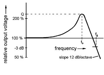
Fig. 4. Fundamental frequency response of a magnetic pickup.
Position and height of the peak vary from type to type
If you know the resonant frequency and height of the resonant peak, you know about 90 percent of a pickup's transfer characteristics; these two parameters are the key to the "secret" of a pickup's sound (some other effects cannot be described using this model, but their influence is less important).
What all this means is that overtones in the range around the resonant frequency are amplified, overtones above the resonant frequency are progressively reduced, and the fundamental vibration and the overtones far below the resonant frequency are reproduced without alteration.
The resonant frequency of most available pickups in combination with normal guitar cables lies between 2,000 and 5,000 Hz. This is the range where the human ear has its highest sensitivity. A quick subjective correlation of frequency to sound is that at 2,000 Hz the sound is warm and mellow, at 3,000 Hz brilliant or present, at 4,000 Hz piercing, and at 5,000 Hz or more brittle and thin. The sound also depends on the height of the peak, of course. A high peak produces a powerful, characteristic sound; a low peak produces a weaker sound, especially with solid body guitars that have no acoustic body resonance. The height of the peak of most available pickups ranges between 1 and 4 (0 to 12 dB), it is dependent on the magnetic material in the coil, on the external resistive load , and on the metal case (without casing it is higher; many guitarists prefer this).
The resonant frequency depends on both the inductance L (with most available pickups, between 1 and 10 Henries) and the capacitance C. C is the sum of the winding capacitance of the coil (usually about 80 - 200 pF) and the cable capacitance (about 300 - 1,000 pF). Since different guitar cables have different amounts of capacitance, it is clear that using different guitar cables with an unbuffered pickup will change the resonant frequency and hence the overall sound.
There are some books that deal especially with electric guitar pickups. They pay much attention to the resistance and the magnet materials. But the resistance is the least interesting magnitude of all. And statements like "Alnico 5 sounds like this, Alnico 2 sounds like that" are completely misleading. Many "pickup experts" have never heard the term "inductance". What you find in those books is an obsolete "geocentric" view on pickups that will never work.
The integral "heliocentric" view on pickups: Pickup, pots in the guitar,
cable capacitance, and amp input impedance are an interactive system that
must not be split up into its parts. If you analyze the properties of the
parts separately you will never understand how the system works as a
whole. The sound material a pickup receives from the strings is not
flavoured by the pickup alone but by the complete system. This includes
the guitar cable.
Another cable, another sound! This is a shame but it is true. You can easily
check it up. A few pickup manufacturers know that fact but they conceal it.
The majority seems to be totally ignorant.
As mentioned earlier, this overview has been simplified to make it easier to understand. Up to this point, it has not taken into account the influence of eddy currents in metal parts. Such currents appear wherever an alternating magnetic field flows through electrically conductive parts. These parts are mostly the cores of magnetic coils � that is, either permanent magnets (in which the currents are relatively weak) or soft iron parts such as screws or fixed slugs (where the currents are stronger). Strong eddy currents can also occur in metal covers; these currents vanish when the covers are removed. To some degree, the currents� strength depends on the dimensions of the metal parts as well as their constituent materials. The decisive factor, however, is the parts� specific resistivity, which is highly variable. There are thousands of iron and steel core types, whose properties can differ widely, resulting in variable frequency transmission characteristics. Metal covers are made of either brass (copper/zinc) or German Silver (copper/zinc/nickel); the latter has a higher specific resistivity and is therefore less conductive to eddy currents. Plastic covers are not conductive. To a lesser extent, eddy currents can also occur in base plates as well as in metal magnets located underneath the coils.
Eddy currents have a threefold effect: First, they reduce resonance superelevation, sometimes to the point of eliminating it completely; secondly, they steepen the slope of frequency transmissions at a height far exceeding the resonant frequency, where 18 dB/octave slopes can be measured. This slope is inversely proportional to the threefold power of the frequency. Thirdly, they cause the frequency transmission curve to drop slightly below the resonant frequency, as shown in Fig. 5:

Fig. 5. Transmission characteristics resulting from strong eddy currents
There have been attempts to measure eddy currents by attaching resistors to the replacement circuit, in parallel to the coil or to the terminals. This method has not been successful, however, for although it does reduce resonance superelevation, it fails to achieve the other two above-mentioned results. A much more effective approach is to divide the coil in two, and to connect only one of the two parts via resistor (R2). The point of division is "virtual" � that is, it does not actually exist, or rather, it cannot be measured directly. This point does not correspond directly to the point at which the two coils in a humbucker are connected; this also holds true for single-coil pickups that have been strongly damped against eddy currents (such as Gibson P90 or DiMarzio "Fat Strat"). The two parts of the coil do not have to be the same size. For practical purposes, identical sizes can be used as a point of departure, but there is no need to keep them identical. The extended replacement circuit is shown in Fig. 6:

Fig. 6. Replacement circuit for a pickup with eddy currents
When you rearrange this setup into an AC signal source by attaching a passive filter, you obtain the configuration shown in Fig. 7:

Fig. 7. Pickup with eddy currents as signal source with attached lowpass filter 3
Basically, there are three different ways to change a guitar's sound as it relates to pickups:
1. Install new pickups. This method is most common, but also the most expensive.
2. Change the coil configuration of the built in pickups. This is possible with nearly all humbucking pickups. Normally, both coils are switched in series. Switching them in parallel cuts the inductance to a quarter of the initial value, so the resonant frequency (all other factors including the guitar cable being equal) will be twice as high. Using only one of the coils halves the inductance, so the resonant frequency will increase by the factor of the square root of 2 (approximately 1.4). In both cases, the sound will have more treble than before. Many humbucking pickups have four output wires - two for each coil - so different coil combinations can be tried without having to open the pickup. Some single coil pickups have a coil tap to provide a similar flexibility.
3. Change the external load. This method is inexpensive but can be very effective. With only a little expense for electronic components, the sound can be shaped within wide limits. Standard tone controls lower the resonant frequency by connecting a capacitor in parallel with the pickup (usually through a variable resistor to give some control over how much the capacitor affects the pickup). Therefore, one way to change the sound is to replace the standard tone control potentiometer with a rotary switch that connects different capacitors across the pickup (a recommended range is 470 pF to 10 nF). This will give you much more sound variation than a standard tone control (Fig. 8).

Fig. 8. Changing the frequency response with
different external capacitors parallel to a pickup coil
These rotary switches are commercially available now, handmade by the author, embedded in epoxy resin (Fig. 9).

Fig. 9. Rotary switch with a selection of different capacitors, embedded in epoxy resin
Also, adding an internal buffer amplifier can isolate the pickup from some of the loading effects of cable capacitance, thus giving a brighter sound with higher resonance frequency and higher peak.
The table correlates some well-known pickups and their electrical characteristics. However, note that pickups are not precision devices and that old pickups in particular (eg. Fender and Gibson pickups of the fifties) vary so much that almost each one sounds different from the next. Thus, the values of the resonant frequency in the table are rounded to the nearest 100 Hz. Also note that peaks become very flat and large below 1,000 Hz. As the height of the resonance peak depends on the external load resistance (volume pot, tone pot and amplifier input resistance), lowering this load (e.g. by switching resistors in parallel to the pickup) lowers the height. For raising the height of the peak, the load resistance must be increased. In many cases this is only possible by installing a FET or other high-impedance preamp in the guitar.
See table: Resonant frequencies of some well-know pickups for various parallel capacitors
4. Install an active electronic circuit that acts as a second-order low-pass filter. This will give you the possibility to adjust the resonant frequency and the resonance height continuously with potentiometers, instead of only in discrete steps. So you can imitate the sound characteristics of many different guitar and bass pickups. These circuits are called „State Variable Filter". The first instrument manufacturer to apply this was Alembic since the seventies, later it was copied by others. Completely mounted circuit boards of this kind, fitting into most common instruments, are available from the author (Fig. 10). They need a 9 V battery for supply, and on some instruments some space inside the body that must be routed.

Fig.10. Active electronic circuit that acts as a second-order low-pass- filter and imitates the sound characteristics of many different guitar and bass pickups
To precisely measure a pickup's frequency response, it would be necessary to measure the vibration of the string and compare it with the output voltage at every frequency. In practice, this is very difficult to do. An alternative to moving the string is to subject the pickup to an outside magnetic field, generated by a transmitting coil. This induces a voltage by changing the magnetic flux through the coils. As the induced voltage in the pickup is proportional to the variation of the magnetic field with time, the driving current through the coil must be inversely proportional to the frequency.
A sine wave voltage feeds an integrator circuit to produce an output voltage that is inversely proportional to frequency. This signal then goes into a power amplifier and then to the transmitting coil that actually couples the signal into the pickup. The coil can consist of a pickup bobbin wound with about 50 turns of enamelled copper wire (approximately 0.5 mm, or 0.02 inches in diameter, no. 24). The exact value is not critical. The coil must be driven with a constant current independent of its impedance. It is mounted above the pickup so that it radiates its magnetic field into the pickup coil(s) as fully as possible. With single coil pickups, the axes must be in line with each other; with humbucking pickups, the axis of the transmitting coil must be perpendicular to the axes of the pickup's coils (Fig. 11).

Fig.11. A transmitting coil radiates its magnetic AC field into the pickup coils. So you can measure the frequency response easily
To plot the response, vary the sine wave frequency from about 100 Hz to 10 kHz and measure the pickup's output voltage with a broad-band multimeter or oscilloscope. The absolute value is not important; what matters is the position of the resonance peak and its height above the overall amplitude at lower frequencies. The effect of different load capacitors (cables) and resistors (pots) is easy to examine with this setup. One of the main advantages of this measuring method is that no modifications on the guitar are necessary, and the pickups need not be removed from the guitar.
This complete measuring arrangement is now available as a commercial instrument. With this, you can easily see what a pickup does with the sound material it gets from strings and body. This is the end of wandering around in the fog. The Pickup Analyzer© (Fig. 12) determines the frequency response, it shows which frequencies are emphasized and which are attenuated - objectively, independent of strings and body, with mounted or loose pickups. How it works: A transmitting coil radiates an alternating magnetic field into the coil(s) of the pickup. While the frequency is varied over the entire audio range, the instrument measures the output voltage of the pickup. The external load conditions can be varied over a wide range: 11 capacitors from 40 pF to 10 nF and four resistors from 125 kOhm to 1 MOhm. Also, the combination of a pickup with a guitar cable can be measured, the influence of different cables on the response is plain to see. Furthermore, it is possible to analyze any modifications on a pickup, such as removing the metal cover or exchanging the magnets for others, or technical defects like short-circuit windings inside the coil. Sample variations of the pickup series can be recognized quickly, deviants can be identified and sorted out. So reclaiming from the manufacturer will have a better chance. The Pickup Analyzer© saves time in development and repairs. Main users are pickup manufacturers, high quality guitarmakers and renowned music shops.

Fig.12. The "Pickup Analyzer"© - the first commercially available measuring instrument for the frequency resonponse of magnetic pickups.
In its first version the Pickup Analyzer worked as a stand-alone device. The figures of frequency and response were read on two seven-segment LED displays. The new second version (Fig. 13) is used in combination with a PC. It is connected via two audio cables to the sound card which works als digital to analog and analog to digital converter.

Fig. 13. The new PC-coupled Pickup Analyzer©
If you run the measuring software you will get the response curves of the pickup on the PC screen. You can easily store it and print it, or send it to another person by e-mail. Fig. 14 and 15 show some results.
Fig. 14 shows the frequency response of a 1972 Fender Stratocaster Pickup with constant capacitive load (470 pF) and eight different Ohmic loads from 10 kOhms to 10 MOhms. It can be seen how different values of pots in the guitar influence the height of the resonance peak. With 47 kOhms or less the peak vanishes.
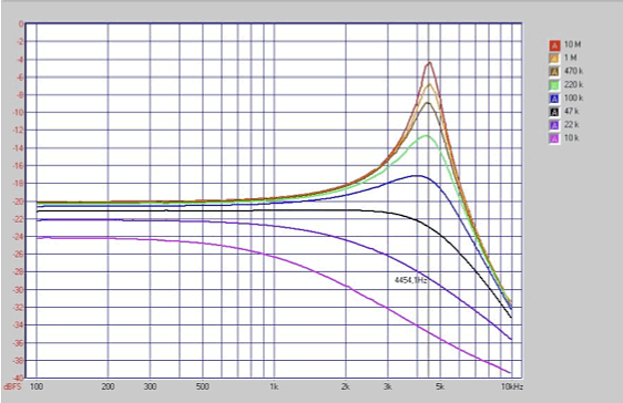
Fig. 14. Response of a Fender Stratocaster pickup with 470 pF load capacitance and different Ohmic loads
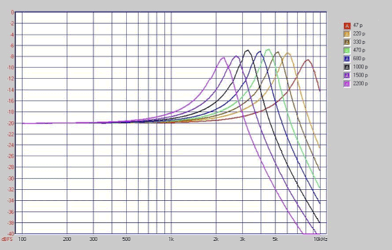
Fig. 15 shows the frequency response of the same pickup, now with constant resistive load and eight different load capacitors from 47 pF to 2200 pF. The resonance frequency and so the tonal characteristics can be easily changed by varying the load capacitance.
For comparison Fig. 16 shows the response of an inferior pickup. This is a Hoyer built around 1970, looking like a humbucker but with only one coil inside, capacitive load 470 pF, five different resistive loads. With the 250 k pots used in this guitar there is no more resonance because of very strong eddy currents in the metal parts. The sound is dull.

The measured result is really precise only for single coil pickups. Humbucking pickups have certain notches at high frequencies, because the vibrations of the strings are picked up at two points simultaneously. High overtones, where the peak of the waveform occurs over one pole and the trough (valley) of the wave occurs over the other, can produce cancellations. These notches are at different frequencies for each string and cannot be described with a single curve. For instance, with standard size humbucking pickups, for the deep E string the notch is at about 3,000 Hz, for the A string at 4,000 Hz. For the high strings the notch is far above the cutoff frequency fg and can hardly be heard.
The effect of the sound difference between one coil and two coils with a humbucker is overestimated by far. The main reason for getting more treble with one coil is that the resonant frequency has been raised because of the halving of the inductance. Sensing the strings at only one point instead of two also has an effect, but this is much smaller. It can only be compared when the resonant frequency is held constant while switching.
Furthermore, this measuring method does not take into consideration the effect of different output voltages of different pickups. In the „crunch" range of a tube amp a loud pickup produces a different tone than a low volume pickup, even when their transfer characteristics are equal. Nevertheless, testing a pickup in this manner gives useful information on its characteristics. With this knowledge, you can find which type of sounds appeal to you the most, and possibly bend and shape the frequency response with external capacitors and resistors to "tune" pickups to your liking (and for the best match to the body and strings).
Finally, the nonlinear distortion of a pickup cannot be measured in this way. It exists, because the relationship between the magnetic flux through the coil(s) and the distance from the magnetic pole to the string follows a hyperbolic curve. So, if the string vibrates in a sine wave (which every harmonic does by itself), additional even harmonics are produced which do not exist in the natural spectrum of the vibration, and as a consequence alter the sound. The resulting distortion depends on the width of the string vibration and can hardly be quantified. The shorter the distance between magnetic pole and string, the stronger it is. This can be heard: With a shorter distance, the sound is more aggressive than with a larger distance. But with too short a distance, the magnets pull the strings, and harmonics are shifted so that they are no longer exact multiples of the fundamental frequency, but a little higher or lower. If this variation is very small, it can sound good and the tone becomes more alive, like with a slight chorus effect. But if it is too large, the sound will be terrible. You will find this problem on many Stratocasters, it is called "Stratitis". The only way to reduce it is to adjust the pickup to be further away from the strings.
© Helmuth E. W. Lemme, Munich, Germany
http://www.gitarrenelektronik.de
The first version of this article was published in the American magazine "Electronic Musician" (edited by Craig Anderton), December 1986, p. 66 - 72.